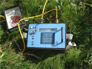
 Electrical Resistivity Tomography (ERT) is an advanced geophysics method used to determine the subsurface’s resistivity distribution by making measurements on the ground surface. ERT data are rapidly collected with an automated multi-electrode resistivity meter. ERT profiles consist of a modeled cross-sectional (2-D) plot of resistivity (Ω·m) versus depth. ERT interpretations, supported by borehole data or alternate geophysical data, accurately represent the geometry and lithology and/or hydrology and/or petrology of subsurface geologic formations.
Electrical Resistivity Tomography measures resistivity. Resistivity, measured in Ω·m, is the mathematical inverse of conductivity. It is a bulk physical property of materials that describes how difficult it is to pass an electrical current through the material. Resistivity measurements can be made with either an alternating current (AC) or a direct current (DC). As resistivity measurements are frequency dependant, care must be taken when comparing resistivity values collected using different techniques.
Clay materials, metallic oxides, and sulphide minerals are the only common sedimentary materials that can carry significant electrical current through the material itself. As such, the resistivity of most near surface sedimentary materials is primarily controlled by the quantity and chemistry of the pore fluids within the material. Any particular material can have a broad range of resistivity responses that is dependant on the level of saturation, the concentration of ions, the presence of organic fluids (such as non aqueous phase liquids, NAPLs), faulting, jointing, weathering, etc.
The general principals that ERT is based on have been in use by geophysicists for almost a century. Recent advances to field equipment and data processing procedures have made rapid 2D surveys routine and 3D surveys possible. Old-style 1D resistivity surveys are still common and are useful on many occasions, but encounter interpretation problems in areas of complex 2D or 3D geology.
For more information on ERT please visit our equipment supplier page at:
Iris Instruments
[x_callout type=”left” title=”Looking for a Solution?” message=”A comprehensive understanding of what lies beneath the surface within the confines of your project area matters. Encountering unforeseen subsurface features can be detrimental to your overall project budget and completion schedule. Shallow geophysics helps to increase your preparedness by providing the capacity to investigate, detect and map mission critical subsurface features throughout a project area, well beyond what can be inferred from borehole drilling programs alone.” button_text=”Contact Us Now” button_icon=”phone-square” href=”https://surfacesearch.com/contact-2/”]