GEOPHYSICAL METHODS
Ground Penetrating Radar
For the past 10 years, ground penetrating radar has been the geophysical method most frequently used to profile subsurface conditions at proposed directional drill crossings in western Canada. This popularity stems from the fact that GPR surveys are relatively inexpensive to obtain and large amounts of data can be acquired through relatively rugged terrain with minimal manpower. GPR surveys generally work well in most alluvial sediment environments and the results represent 2-dimensional cross-section imagery of subsurface conditions.
Ground penetrating radar is a general term to describe methods that use radio waves (10 MHz – 1.2 GHz) to probe subsurface objects or geologic features. GPR is a non-invasive electromagnetic (EM) geophysical technique for subsurface exploration and characterization. GPR systems transmit impulse electromagnetic energy (i.e. radio waves) into the ground and detect echoes, or reflected wave front energy, at the ground surface. This process is somewhat similar to p-wave seismic reflection methods and theoretical similarities exist between the kinematic properties of elastic and electromagnetic wave propagation. GPR is capable of profiling sediment stratigraphy and bedrock surface elevations throughout the length of proposed pipeline crossings. It can be used to detect boulder deposits at depth as well as profile the geometry and distribution of sand, gravel, silt and clay deposits.
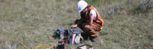
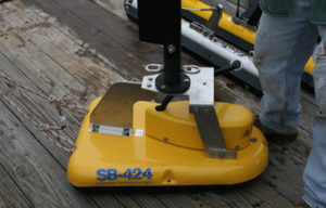
GPR data collection consists of taking readings at discreet intervals (e.g. every 0.5 m) along surveyed transects. The most common type of survey is ‘optimum offset profiling’, where the transmitter and receiver antenna are kept at a constant distance from one another while they are moved along the survey line. Data collection is controlled from a notebook computer and results can be viewed in real time on screen. On land, GPR data is collected by moving the antennas by hand and over open water the antennas can either waded across channel areas, or mounted off the sides of a boat.
The GPR method is effective in profiling sediment conditions that are electrically resistive (e.g. dry silt, sand, gravel, cobbles and boulders). In areas where electrically conductive sediment conditions exist (e.g. wet clay sediments), GPR signals are attenuated within the subsurface, resulting in reduced depth of signal penetration. Signal penetration depths are somewhat dependant upon antenna frequencies used to probe the subsurface. As a general rule, lower frequency antennas (e.g. 12.5 – 50 MHz) produce the greatest depth of penetration, but with lower vertical resolution compared to data collected with higher frequency antennas (e.g. 100-450 MHz).
Seismic Refraction
Seismic refraction surveys are primarily used to provide depth to bedrock information and estimates of rock strength and rippability. Like GPR surveys, seismic refraction data are relatively inexpensive to obtain because of minimal manpower and relatively low-cost equipment requirements.
Seismic refraction surveying consists of an in-line geophone array recording the arrival time of subsurface acoustic energy head-waves. The waves are generated from both ends of, and at intermediate locations within the geophone array. Common energy sources used for shallow surveys include striking a sledgehammer against a steel plate on the ground, or black powder blank explosives (e.g. buffalo gun) triggered in shallow holes (e.g. 30 cm). For engineering surveys, between 12 and 48 geophones are commonly used to record ground movement at surface.
Depth estimates for refracted energy arrivals can be calculated using the measured head-wave arrival times and known geophone array geometry. Seismic refraction is effective in areas where acoustic energy propagation velocities increase with depth and where there is a significant velocity contrast between upper layer material (e.g. alluvial sediments) overlying more competent lower layer material (e.g. bedrock, ablation till).
The primary limitation of seismic refraction is that it is dependent upon the assumption (for a given survey area) that signal velocities will increase with depth as head-waves propagate through the ground. In instances where low-velocity layers are buried below high-velocity layers (e.g. gravel deposits buried below ablation till sediments) the method will fail to detect the low velocity layer (i.e. hidden layer) and produce erroneous refractor arrival depth estimates.
An additional limitation is that the method requires proper coupling between the geophones and the ground. In areas such as cobble and boulder bars it may not be possible to obtain good ground coupling. Over active channel areas, refraction survey data is prone to significant noise interference from moving water and in most instances data collection is logistically impractical to obtain.
A further requirement of refraction surveys is that the geophone array length must at least 5 to 10 times the distance to the target depth zone of interest. The geophone array must also be in a straight-line to avoid errors in calculated refractor depths.
Electrical Resistivity Tomography
Electrical resistivity tomography (ERT) surveys are relatively new compared with GPR and seismic refraction, however, in the world of near surface geophysics, the ERT method is quickly emerging as a powerful means of obtaining subsurface geologic and hydrogeologic information.
ERT is an advanced geophysical technique used to determine the subsurface’s electrical resistivity distribution by making measurements on the ground surface. Resistivity, measured in Ωm, is the mathematical inverse of conductivity and represents a bulk physical property that describes how difficult it is to pass an electrical current through the material.
ERT involves introducing a DC electrical current into the ground with two electrodes and measuring the voltage drop across the surface of the ground with two other electrodes. Because electrical flow disperses throughout the ground, these surface measurements provide information about the electrical character of materials below the earth’s surface. The primary control on the depth of investigation for a measurement is the distance between the electrodes. ERT profiles are produced by modeling the data from a series of measurements at different depths and locations along a survey line.
ERT data are rapidly collected with an automated multi-electrode resistivity meter. ERT profiles consist of a modeled cross-sectional (2-D) plot of resistivity (Ωm) versus depth. ERT interpretations, supported by borehole data or alternate geophysical data, provide cross-section imagery about the geometry and lithology of subsurface features including bedrock and alluvial sediments.
Like seismic refraction, the ERT method requires straight-line transects which must be at least 5 to 10 time longer than desired target depths. For the method to be successful, good (electrical) contact between the electrodes and the ground must be established. In areas where electrically resistive sediment conditions occur at ground surface (e.g. dry sand, ice) additional effort may be required to improve electrode ground contact conditions.
Because electrical resistivity is a bulk physical property of materials, ERT profiles provide a great deal of information about the identity of the different materials in the subsurface. However, for the same reason, ERT profiles only provide a rough indication of the location of the boundaries between the different materials encountered in the subsurface. Resolution of ERT profiles is approximately ½ of the electrode spacing.