[cs_content][cs_section parallax=”false” style=”margin: 0px;padding: 45px 0px;”][cs_row inner_container=”false” marginless_columns=”false” style=”margin: 0px auto;padding: 0px;”][cs_column fade=”false” fade_animation=”in” fade_animation_offset=”45px” fade_duration=”750″ type=”1/1″ style=”padding: 0px;”][cs_text]The conclusion and the results of our 3 part series on the application of near-surface geophysics. You can read part one here, and part two here.
OVERLAPPING GEOPHYSICAL SURVEYS
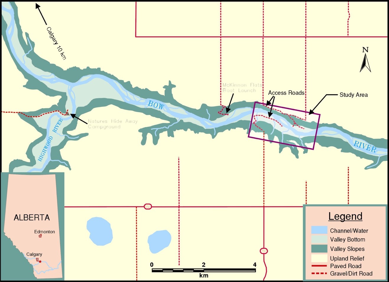
To compare the results from each of the geophysical methods described above, overlapping surveys were conducted at a study site located within the Bow River valley approximately 15 km downstream from Calgary (Figure 1). The primary objective of this field experiment was to determine the capabilities of each method with respect to detecting or imaging subsurface features relevant to the construction and engineering design of directionally drilled pipeline river crossings. In addition, we wanted to determine whether there would be any benefit to obtaining geophysical data from more than one geophysical method at a potential pipeline river crossing.
The site was selected because of its proximity to Calgary and because borehole data from a previous geotechnical investigation completed in 1996, was available for use as ground-truth information for the geophysical results.
Within this reach of the river, the valley is approximately 1 km wide, with the valley bottom situated 90 m below the surrounding upland. Both valley walls are bedrock controlled and are steep (i.e. 30 to > 45 degrees locally).
The upland is covered with glacial till deposits overlying sandstone and shale bedrock of the Paskapoo – Porcupine Hills Formation (Moran, 1986). Outcrop exposures, visible along the bottom half of both valley walls, show that bedrock has a horizontal structure, and is comprised of weathered shale, with some indurate layers of sandstone.
Borehole data obtained within the study site indicates that the sediment stratigraphy consists of: overbank sit, sand and clay (0-4m), and coarse gravel and cobbles (4-12m) overlying siltstone and shale bedrock. One borehole revealed evidence of clay diamicton sandwiched in-between a surface deposit of silt and a basal unit of gravel overlying bedrock.
Vegetation conditions within the valley bottom consist of willows, poplar and cottonwood stands along the channel banks. Towards the toe of the valley walls, the trees and shrubs give way to grasslands with widely spaced clusters of shrubs.
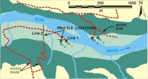
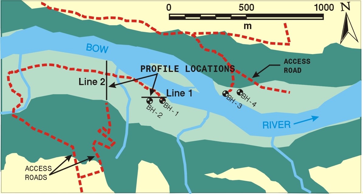
Geophysical data were acquired across two transect lines on the south side of the main channel (Figure 2). The transect locations were surveyed using a handheld GPS unit. Horizontal position reference for all of the geophysical measurements was surveyed using a ground measurement chain.
The first geophysical transect (Line 1) runs west to east parallel to the valley. It intersects two boreholes from the previous geotechnical investigation. The transect has negligible topographic relief and covers a distance of 140 m with the eastern end of the line situated near the south bank of the river channel. The west end of Line 1 is located well into the valley bottom floodplain.
The second geophysical transect (Line 2) is situated approximately 300 m west of Line 1, and runs north to south perpendicular to the valley. Line 2 has approximately 4 m of ground relief and is 250 m long. The northern end of the line is at the top of a cutbank on the south side of the river channel. The south end of the line extends up to the toe of the valley wall.
The boreholes used as a guide for interpretation of the geophysical results are located adjacent to Line 1. The borehole strip logs are overlain onto the geophysical results and interpretations in Figures 3 through 7. Just west of 0+00, borehole BH-1 encountered a silt/gravel interface at a depth of 4.5 m and a gravel/siltstone bedrock interface at a depth of 8.7 m. At 0+50, borehole BH-2 encountered a silt/gravel interface at a depth of 3.9 m and a gravel/siltstone bedrock interface at a depth of 9.2 m.
RESULTS
Line1 and Line 2 were surveyed by ground penetrating radar, seismic refraction and electrical resistivity tomography.
For the GPR surveys we used a Pulse-EKKO ground radar system outfitted with 25 MHz antennas. Optimum offset reflection profile data were acquired at 0.5 m station intervals over both transects with a transmitter to receiver antenna separation distance of 5 m. The GPR data were processed and plotted using Pulse-EKKO system software.
The seismic refraction surveys were completed using a 60-channel Geometrics Strataview seismograph connected to 10 Hz geophones at 4 m interval spacings. Sledgehammer impacts on a metal plate were used as the energy source. Data processing consisted of displaying the seismic records graphically on computer and digital picking of first break arrivals. Refractor depths were calculated using Gremix seismic refraction interpretation software.
The ERT data was collected using an AGI 56-electrode Sting/Swift ground resistivity system with 2 m electrode spacings. The resistivity measurements were based on the Wenner electrode array. The ERT data were processed using RES2D inversion software, which produced cross-section contour models depicting spatially corrected ground resistivity values.

The GPR results for Line 1 (Figure 3) are interpreted to have profiled a sedimentary interface between silt and gravel deposits. Below the direct and refracted arrivals in the GPR profile, a laterally continuous, high-amplitude reflection event is observed to coincide with the silt/gravel interface identified in the borehole logs. Below this event, the GPR signals are significantly attenuated and the method is believed to have only detected the bedrock surface from 0+00 to 0+50 below the gravel deposits.

The seismic refraction results for Line 1 (Figure 4) are shown to contain calculated depths of a single refractor layer interpreted throughout much of the transect. Seismic head-wave velocities for the ground roll were calculated to be approximately 450 m/sec while refracted arrival velocities ranged from approximately 2250 to 2500 m/sec over the length of the profile. The calculated refractor depths are shown to range from 7.8 m at 0+20 to 12.1 m at 0+90. Using the borehole logs as a guide, the refracted arrival is interpreted to represent the bedrock surface, which is shown trending to greater depths towards the west end of the profile.

The modeled results from the ERT data collected over Line 1 (Figure 5) are interpreted to depict a three layer geologic sequence to a depth of 20 m. The upper 2.5 to 5 m has a resistivity from 50 – 115 Ωm, which is typical of silts and clays. The next 5 to 10 m has a resistivity from 125 – 1400 Ωm, which is typical of sand or gravel. The lower-most layer, which begins at approximately 10 to 15 m below ground level and extends to the bottom of the ERT profile, has very low resistivity (< 50 Ωm). Very low resistivity values are typical of clay, groundwater contamination, or conductive bedrock. Using the borehole logs as a guide, the ERT data can be interpreted to represent silt deposits overlying gravel deposits overlying siltstone bedrock. The ERT data also suggests that the gravel deposit is thickening and coarsening towards the west with a corresponding increase in bedrock depths. Bedrock appears to dip from approximately 10 m below ground surface at 0+50 to a depth of 15 m below ground surface by 0+100.

By overlaying the results from each survey method (Figure 6) a more detailed and complete interpretation of the subsurface conditions below Line 1 can be achieved (Figure 7). The GPR data provides high-resolution depth estimates for the silt/gravel interface as well as bedrock depths near the east end of the profile. The seismic refraction data provides depth to bedrock information in areas where GPR signal penetration was limited, and further indicates that bedrock trends to greater depths towards the west end of the profile. Although the vertical resolution of the ERT results are not as precise as compared with the GPR or seismic refraction results, the method provides insight into overburden sediment characterizations and supports the interpretation of bedrock trending to greater depths towards the west end of the profile.

The GPR results obtained for Line 2 (Figure 8) are interpreted to provide a profile view of sedimentary features throughout much of the transect as well as the bedrock surface between 0+00 and 1+00. The interpreted bedrock surface in this area of the transect is represented by laterally continuous reflection event occurring at depths ranging from approximately 7.5 to 10.5 m below ground level. From 1+00 to 2+50 the GPR data is observed to contain numerous high-frequency signal events interpreted as above ground reflectors (i.e. background noise). The GPR data within this reach of the transect is difficult to interpret because of discontinuities in signal reflection events and a poor signal to noise ratio in the data. This change in response is likely attributable to the presence of an electrically conductive sediment layer near surface (between 1+00 and 2+50).

The seismic refraction results for Line 2 (Figure 9) are shown to contain calculated depths of a single refraction layer interpreted throughout much of the transect. Seismic head-wave velocities for the ground roll were calculated to range from approximately 450 to 700 m/sec while refracted arrival velocities ranged from approximately 2250 to 2500 m/sec over the length of the profile. The calculated refractor depths are shown to range from 3.8 m at 2+10 to 11.5 m at 0+80. Using the interpreted results from Line 1 as a guide, the refracted arrival is interpreted to represent the bedrock surface, which trends to greater depths towards the middle of the profile, and then to more shallow depths at the south end of the profile.

The modeled results from the ERT data collected over Line 2 (Figure 10) are interpreted to depict a three layer geologic sequence below the transect to a depth of 20 m. The upper layer is evident from 0+50 to the end of the profile at 1+90 and contains moderately low resistivity values (50 – 115 Ωm). The intermediate layer is evident throughout the profile and contains relatively high resistivity values (125 – 1400 Ωm). The lower-most layer,
beginning at approximately 10 to 15 m below ground level, through to the bottom of the ERT profile contains low resistivity values (< 50 Ωm). Using the results from Line 1 as a guide, the ERT data can be interpreted to delineate the spatial distribution of silt, clay and gravel deposits as well as estimations of bedrock depths.

By overlaying the results from each survey method for Line 2 (Figure 11) a more detailed and complete interpretation of the subsurface conditions below Line 2 can be achieved (Figure 12). The GPR data provides high-resolution depth estimates for the silt/gravel interface as well as bedrock
depths near the north end of the profile. The seismic refraction data provides depth to bedrock estimates in areas where GPR signal penetration is limited. The ERT results provide sediment characterization information and support depth to bedrock estimations. Together, the results are interpreted to reveal a channel scour (into bedrock) feature from 0+50 to 1+10 and a trend towards gradually rising bedrock elevations towards the toe of the south valley. Towards the river-side end of the profile sediment conditions are interpreted to consist primarily of gravel deposits through to bedrock.

CLOSING REMARKS
The results from the geophysical field survey experiments completed within the Bow River valley help demonstrate the capabilities and limitations for each method used (GPR, seismic refraction and ERT) to detect and/or image subsurface features relevant to geotechnical evaluations of proposed pipeline river crossings. Overlapping geophysical surveys allow interpretation of greater detail of subsurface features, at a higher degree of confidence.

Used alone, each method is susceptible to producing either incomplete or misleading interpretations of the subsurface. The seismic refraction method for example, can be used to determine depth to bedrock information, but is less effective in providing overburden sediment characterizations. In the cases discussed here, seismic refraction provided an excellent profile of the bedrock surface but did not differentiate between the silt and gravel layers. GPR is capable of providing the best vertical resolution of any near surface geophysical method, however electrically conductive sediment conditions at surface can reduce depth of penetration so much that targets of interest are not reached. In the cases discussed here, GPR provided an excellent profile of the silt/gravel contact but did not reach bedrock in many areas. ERT is capable of providing information about the identity of subsurface materials but has poor vertical resolution. In the cases discussed here, ERT confirmed and extended the lithology information from the boreholes, but could not provide vertical resolution better than ±1 m.
By combining GPR, seismic refraction and ERT, the limitations of each were overcome. A final detailed interpretation includes the depth of the silt/gravel interface and the depth of the gravel/bedrock interface. Though these methods may not respond well or even be feasible throughout all areas of a river valley investigation, their combined potential is believed to represent an improvement over using any single method alone.
Acknowledgments
The authors would like to thank Dr. D.G. Smith, Dr. J.M. Maillol, Malcolm Bertrand and Eric Gallant from the departments of Earth Science and Geology/Geophysics at the University of Calgary for their support and assistance with field data collection.
References
Moran, S. R., 1986, Surficial Geology of the Calgary urban area, in Bulletin No. 53, Alberta Research Council: Terrain Sciences Department, pp. 17-18.[/cs_text][/cs_column][/cs_row][/cs_section][cs_section parallax=”false” style=”margin: 0px;padding: 45px 0px;”][cs_row inner_container=”false” marginless_columns=”false” style=”margin: 0px auto;padding: 0px;”][cs_column fade=”false” fade_animation=”in” fade_animation_offset=”45px” fade_duration=”750″ type=”1/1″ style=”padding: 0px;”][x_slider animation=”slide” slide_time=”7000″ slide_speed=”1000″ slideshow=”false” random=”false” control_nav=”false” prev_next_nav=”true” no_container=”false” ][x_slide]